- SKU:
- MS132-1.6-HKF1-11
- UPC:
- 4013614404467
- Weight:
- 0.65 LBS
- Width:
- 1.77 in
- Height:
- 3.54 in
- Depth:
- 3.42 in
- Rated Operational Current:
- 1.60 Amperage
- Trip Class:
- 10
- Terminal Type:
- Screw Terminals

Representative image shown
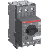
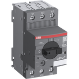
MS132-1.6-HKF1-11
Manual Motor Starter (1.0-1.6A)
$313.99
Factory New
ABB
ABB, Manual Motor Starter, 45 mm, 1.00 A to 1.60 A setting range, pre-assembled front-mounted HKF1-11 (1NO/1NC) auxiliary contact, provides fuse-less motor protection up to 0.55 kW at 400 VAC
Representative image shown
Product Details
Complete Your Build
verified
Verified fit
These products are compatible with the
Auxiliary Contacts
Signaling Contacts
Shunt Trips
Undervoltage Releases
Busbars
Terminal Blocks
Enclosures
Shafts

Build My Enclosure
Total price: $0
Description
Description
The MS132-1.6-HKF1-11 manual motor starter (also known as motor protection circuit breaker or manual motor protector) is a compact 45 mm width device with a rated operational current of Ie = 1.60 A and a pre-assembled front mounted auxiliary contact HKF1-11. This device is used to manually switch on and off motors and to protect them reliably and without the need for a fuse from short-circuits, overload and phase failures. The manual motor starter offers a rated service short-circuit breaking capacity Ics = 100 kA at 400 VAC and trip class 10. Further features are the build-in disconnect function, temperature compensation, trip-free mechanism and a rotary handle with a clear switch position indication. The manual motor starter is suitable for three- and single-phase applications. The handle is lockable to protect against unauthorized changes. Auxiliary contacts, signaling contacts, undervoltage releases, shunt trips, 3-phase bus bars, power in-feed blocks and terminal spacers are available as accessory.
Specifications
Specifications
Technical |
|
| Rated Service Short-Circuit Breaking Capacity (Ics): |
(230 V AC) 100 kA
(250 V DC) 3 Poles in Series 10 kA
(400 V AC) 100 kA
(440 V AC) 100 kA
(500 V AC) 100 kA
(690 V AC) 100 kA
|
| Rated Ultimate Short-Circuit Breaking Capacity (Icu): |
(230 V AC) 100 kA
(400 V AC) 100 kA
(440 V AC) 100 kA
(500 V AC) 100 kA
(690 V AC) 100 kA
|
| Rated Instantaneous Short-Circuit Current Setting (Ii): | 20 A |
| Setting Range: | 1.0 ... 1.6 A |
| Rated Operational Power AC-3 (Pe): | (400 V) Three Phase 0.55 kW |
| Rated Operational Power AC-3e (Pe): | (400 V) Three Phase 0.55 kW |
| Rated Operational Voltage: |
Main Circuit 690 V AC
Main Circuit 250 V DC
|
| Rated Operational Current (Ie): | 1.6 A |
| Rated Operational Current AC-3 (Ie): | 1.6 A |
| Rated Operational Current AC-3e (Ie): | 1.6 A |
| Rated Operational Current DC-5 (Ie): | 1.6 A |
| Rated Frequency (f): |
Main Circuit 50 Hz
Main Circuit 60 Hz
|
| Operating Frequency (fsw): | 0 ... 400 Hz |
| Rated Impulse Withstand Voltage (Uimp): | Main Circuit 6 kV |
| Rated Insulation Voltage (Ui): | 690 V |
| Power Loss: | at Rated Operating Conditions per Pole 0.6 ... 1.7 W |
| Number of Poles: | 3P |
| Mounted Auxiliary Contacts: | 1 NO, 1 NC |
| Conventional Free-air Thermal Current (Ith): | Main Circuit 1.6 A |
| Degree of Protection: |
Housing IP20
Main Circuit Terminals IP10
|
| Pollution Degree: | 3 |
| Electrical Durability: | 50000 cycle |
| Mechanical Durability: | Nr. Operations 100000 cycle |
| Terminal Type: | Screw Terminals |
| Connecting Capacity Main Circuit: |
Flexible with Ferrule 1/2x 0.75 ... 2.5 mm²
Flexible with Insulated Ferrule 1/2x 0.75 ... 2.5 mm²
Flexible 1/2x 0.75 ... 2.5 mm²
Rigid 1/2x 1 ... 4 mm²
|
| Connecting Capacity Auxiliary Circuit: |
Flexible with Ferrule 1/2x 0.75 ... 1.5 mm²
Flexible with Insulated Ferrule 1/2x 0.75 ... 1.5 mm²
Flexible 1/2x 0.75 ... 1.5 mm²
Rigid 1/2x 1 ... 1.5 mm²
|
| Tightening Torque: | Main Circuit 0.8 ... 1.2 N·m |
| Wire Stripping Length: |
Auxiliary Circuit 8 mm
Main Circuit 9 mm
|
| Recommended Screw Driver: | Pozidriv 2 |
| Mounting Position: | 1 ... 6 |
| Mounting on DIN Rail: |
TH35-15 (35 x 15 mm Mounting Rail) acc. to IEC 60715
TH35-7.5 (35 x 7.5 mm Mounting Rail) acc. to IEC 60715
|
| Minimum Mounting Distance: |
Electrical Conductive Board, Horizontal - Up to 400 V 0 mm
Electrical Conductive Board, Horizontal - Up to 690 V 1.5 mm
Electrical Conductive Board, Vertical 75 mm
Other Device Same Type, Horizontal 0 mm
Other Device Same Type, Vertical 150 mm
|
| Contact Position Indication: | ON / OFF / TRIP |
| Standards: |
IEC/EN 60947-1
IEC/EN 60947-2
IEC/EN 60947-4-1
IEC/EN 60947-5-1
UL 60947-1
UL 60947-4-1
IEC 60335-2-40 A2L
|
| Remarks: | UL508 Self-Protected Combination Motor Controller (Type E) in combination with feeder block S1-M3-xx |
Technical UL/CSA |
|
| Short-Circuit Current Rating (SCCR): |
Manual Self-Protected Combination Controllers (Type E), (480Y / 277 V AC) 65 kA
Manual Self-Protected Combination Controllers (Type E), (600Y / 347 V AC) 47 kA
Any UL Listed Fuses or Circuit-Breakers, Group Installations (480 V AC) 65 kA
Any UL Listed Fuses or Circuit-Breakers, Group Installations (600 V AC) 47 kA
Any UL Listed Fuses or Circuit-Breakers, Motor Disconnect (480 V AC) 65 kA
Any UL Listed Fuses or Circuit-Breakers, Motor Disconnect (600 V AC) 47 kA
Any UL Listed Fuses or Circuit-Breakers, Tap Conductor Protection in Group Installations (480Y / 277 V AC) 65 kA
Any UL Listed Fuses or Circuit-Breakers, Tap Conductor Protection in Group Installations (600Y / 347 V AC) 47 kA
|
| Maximum Operating Voltage UL/CSA: |
Auxiliary Circuit 250 V AC/DC
Main Circuit 600 V AC
|
| Horsepower Rating UL/CSA: |
(440 ... 480 V AC) Three Phase 0.75 Hp
(550 ... 600 V AC) Three Phase 0.75 Hp
|
| Full Load Amps Motor Use: |
(200 V AC) Three Phase 1.6 A
(208 V AC) Three Phase 1.6 A
(220 ... 240 V AC) Three Phase 1.6 A
(440 ... 480 V AC) Three Phase 1.6 A
|
| Locked Rotor Amps: |
(200 V AC) Three Phase 9.6 A
(208 V AC) Three Phase 9.6 A
(220 ... 240 V AC) Three Phase 9.6 A
(440 ... 480 V AC) Three Phase 9.6 A
(550 ... 600 V AC) Three Phase 9.6 A
|
| General Use Rating UL/CSA: | (600 V AC) 1.6 A |
| Connecting Capacity Main Circuit UL/CSA: |
Flexible 1/2x 16-12 AWG
Stranded 1/2x 16-12 AWG
|
| Connecting Capacity Auxiliary Circuit UL/CSA: |
Flexible 1/2x 16-14 AWG
Stranded 1/2x 16-14 AWG
|
| Tightening Torque UL/CSA: |
Auxiliary Circuit 7 in·lb
Main Circuit 10 ... 12 in·lb
|
| Contact Rating UL/CSA: |
B300
R300
|
Environmental |
|
| Ambient Air Temperature: |
Around the Enclosure 0 ... +40 °C
Operation -25 ... +70 °C
Operation Compensated -25 ... +60 °C
Storage -50 ... +80 °C
|
| Ambient Air Temperature Compensation: | Yes |
| Maximum Operating Altitude Permissible: |
2000 m
|
| Resistance to Shock acc. to IEC 60068-2-27: | 11 ms Pulse 25g |
| Resistance to Vibrations: | 5g 3 ... 150 Hz |
Documents for
- Installation Instructions MS132/MS132-B
- Time Current Characteristic Curve MS132-1.6
- l2t Characteristic @400V MS132
- l2t Characteristic @500V MS132
- l2t Characteristic @690V MS132
- Cut-off Current Characteristic @400V MS132
- Cut-off Current Characteristic @690V MS132
- CAD Dimensional Drawing
- Dimension Diagram