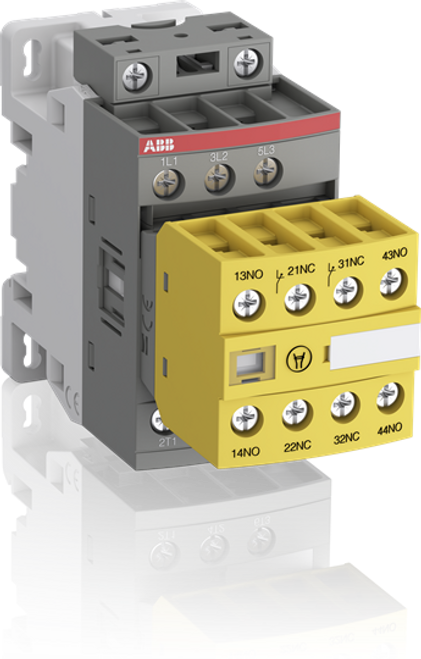
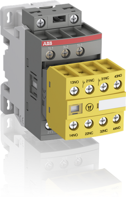
The AFS16-30-22-11 is a 3 pole - 690 V IEC or 600 V UL contactor with fixed 2 N.O + 2 N.C. front mounted auxiliary contact blocks with screw connections, controlling motors up to 7,5 kW / 400 V AC (AC-3) or 10 hp / 480 V UL and switching power circuits up to 30 A (AC-1) or 30 A UL general use. AFS contactors can be easily integrated in machine manufacturer’s systems complying with main standards EN ISO 13849 and EN 62061 - guaranteeing the safe use of your machinery and equipment. An easily identifiable yellow low energy auxiliary contact block ensures the status feedback circuits required in machine safety applications. Thanks to the AF technology, the contactor has a wide control voltage range (24 ... 60 V), managing large control voltage variations, reducing panel energy consumption and ensuring distinct operations in unstable networks. Furthermore, surge protection is built-in, offering a compact solution. AF contactors have a block type design, can be easily extended with add-on auxiliary contact blocks and an additional wide range of accessories.
Specifications
Dimensions |
|
|---|---|
| Product Net Width | 45 mm |
| Product Net Depth / Length | 110.5 mm |
| Product Net Height | 86 mm |
Technical |
|
| Number of Main Contacts NO | 3 |
| Number of Main Contacts NC | 0 |
| Number of Auxiliary Contacts NO | 2 |
| Number of Auxiliary Contacts NC | 2 |
| Standards | IEC 60947-1 / 60947-4-1 and EN 60947-1 / 60947-4-1, UL 508, CSA C22.2 N°14 |
| Rated Operational Voltage | Auxiliary Circuit 690 V Main Circuit 690 V |
| Rated Frequency (f) | Auxiliary Circuit 50 / 60 Hz Main Circuit 50 / 60 Hz |
| Conventional Free-air Thermal Current (Ith) | acc. to IEC 60947-4-1, Open Contactors q = 40 °C 35 A acc. to IEC 60947-5-1, q = 40 °C 16 A |
| Rated Operational Current AC-1 (Ie) | (690 V) 40 °C 30 (690 V) 60 °C 30 A (690 V) 70 °C 26 |
| Rated Operational Current AC-3 (Ie) | (415 V) 60 °C 18 A (440 V) 60 °C 18 A (500 V) 60 °C 15 A (690 V) 60 °C 10.5 A (380 / 400 V) 60 °C 18 A (220 / 230 / 240 V) 60 °C 18 A |
| Rated Operational Power AC-3 (Pe) | (400 V) 7.5 kW (415 V) 9 kW (440 V) 9 kW (500 V) 9 kW (690 V) 9 kW (380 / 400 V) 7.5 kW (220 / 230 / 240 V) 4 kW |
| Rated Operational Current AC-15 (Ie) | (500 V) 2 A (690 V) 2 A (24 / 127 V) 6 A (220 / 240 V) 4 A (400 / 440 V) 3 A |
| Rated Short-time Withstand Current Low Voltage (Icw) | at 40 °C Ambient Temp, in Free Air, from a Cold State 10 s 150 A at 40 °C Ambient Temp, in Free Air, from a Cold State 15 min 35 A at 40 °C Ambient Temp, in Free Air, from a Cold State 1 min 60 A at 40 °C Ambient Temp, in Free Air, from a Cold State 1 s 300 A at 40 °C Ambient Temp, in Free Air, from a Cold State 30 s 80 A for 0.1 s 140 A for 1 s 100 A |
| Maximum Breaking Capacity | cos phi=0.45 (cos phi=0.35 for Ie > 100 A) at 440 V 250 A cos phi=0.45 (cos phi=0.35 for Ie > 100 A) at 690 V 106 A |
| Maximum Electrical Switching Frequency | (AC-1) 600 cycles per hour (AC-15) 1200 cycles per hour (AC-2 / AC-4) 300 cycles per hour (AC-3) 1200 cycles per hour (DC-13) 900 cycles per hour |
| Rated Operational Current DC-13 (Ie) | (24 V) 6 A / 144 W (48 V) 2.8 A / 134 W (72 V) 1 A / 72 W (110 V) 0.55 A / 60 W (125 V) 0.55 A / 69 W (220 V) 0.27 A / 60 W (250 V) 0.27 A / 68 W (400 V) 0.15 A / 60 W (500 V) 0.13 A / 65 W (600 V) 0.1 A / 60 W |
| Rated Insulation Voltage (Ui) | acc. to IEC 60947-4-1 and VDE 0110 (Gr. C) 690 V acc. to UL/CSA 600 V |
| Rated Impulse Withstand Voltage (Uimp) | 6 kV |
| Maximum Mechanical Switching Frequency | 3600 cycles per hour |
| Rated Control Circuit Voltage (Uc) | 50 Hz 24 ... 60 V 60 Hz 24 ... 60 V DC Operation 20 ... 60 V |
| Operate Time | Between Coil De-energization and NC Contact Closing 13 ... 98 ms Between Coil De-energization and NO Contact Opening 11 ... 95 ms Between Coil Energization and NC Contact Opening 38 ... 90 ms Between Coil Energization and NO Contact Closing 40 ... 95 ms |
| Mounting on DIN Rail | TH35-7.5 (35 x 7.5 mm Mounting Rail) acc. to IEC 60715 TH35-15 (35 x 15 mm Mounting Rail) acc. to IEC 60715 |
| Mounting by Screws (not supplied) | 2 x M4 screws placed diagonally |
| Connecting Capacity Main Circuit | Flexible with Ferrule 1/2x 0.75 ... 6 mm² Flexible with Insulated Ferrule 1x 0.75 ... 4 mm² Flexible with Insulated Ferrule 2x 0.75 ... 2.5 mm² Rigid 1/2x 1 ... 6 mm² |
| Connecting Capacity Auxiliary Circuit | Flexible with Ferrule 1/2x 0.75 ... 2.5 mm² Flexible with Insulated Ferrule 2x 0.75 ... 1.5 mm² Flexible with Insulated Ferrule 1x 0.75 ... 2.5 mm² Rigid 1/2x 1 ... 2.5 mm² |
| Connecting Capacity Control Circuit | Flexible with Ferrule 1/2x 0.75 ... 2.5 mm² Flexible with Insulated Ferrule 1x 0.75 ... 2.5 mm² Flexible with Insulated Ferrule 2x 0.75 ... 1.5 mm² Rigid 1/2x 1 ... 2.5 mm² |
| Wire Stripping Length | Auxiliary Circuit 10 mm Control Circuit 10 mm Main Circuit 10 mm |
| Degree of Protection | acc. to IEC 60529, IEC 60947-1, EN 60529 Auxiliary Terminals IP20 acc. to IEC 60529, IEC 60947-1, EN 60529 Coil Terminals IP20 acc. to IEC 60529, IEC 60947-1, EN 60529 Main Terminals IP20 |
| Terminal Type | Screw Terminals |


